
Even in the early 1970's I was interested in coaxial speakers. Lusted after those good old Altec coax speakers. And later coax models such as Urie and Fostex. However, my main use at the time were keyboard and PA speakers. The old classic coax speakers didn't have much low bass and had rather low power handling compared to non-coax offerings by the usual suspects. The coax speakers were somewhat expensive compared to non-coax components. Worried that coax speakers on-stage would have excessive risk of blowing up. And perhaps have to truck too many coax speakers in order to compensate for the fairly low power rating. Seemed risky and non-cost-effective to use coax speakers live, so I never owned any.
Have most-enjoyed playing or tracking thru good quality PA-type speakers. Perhaps conditioned by decades playing live for a living, expecting keys to have a “big sound”. When I play at home on nice small studio monitors-- The small studio monitors I've tried tend to sound small and plastic for live playing. It doesn't bug me to do recreational listening, mixing, or to record other musicians with small monitor speakers. But playing keys or bass thru small studio monitors is like watching the Jaws movie on a smart phone. No one is impressed by the giant one-inch shark!
Tis difficult to explain. My small studio monitors are clean and flat enough. In the nearfield they can be cranked clean to painful levels. But for whatever reason they have a “small sound” for live playing or self-tracking.
Decided to try PA-like coax nearfield monitors-- Decent-sized midwoofers and real horns with some balls. No weenie 1 inch dome tweeters.
Pictured is the previous setup with the old JBL 8" 2-ways "soft soffited" or whatever you want to call it-- Surrounded by foam and polyester batts, at a 45 degree toe-in. The entire “inside” of the corners surrounding the speakers are filled with medium-density open cell foam. I had a local foam company make them to fill the entire corner surrounding the jbl speakers. The foam devices behind the polyester batts look similar to the Stonehenge stage props from the Spinal Tap movie.

This seemed to work rather well as very-nearfield texas-sized headphones. The soft-soffits improved both the perceived sound and the measured frequency response-- Primarily in the mids and highs. These soft-soffits reduced the amplitude of “fine-grained frequency response squiggles” in frequency response plots. Gearslutz.com member RyanC suggested that soft-soffits may have improved the fine-detail frequency response by reducing speaker cabinet diffraction. I do not know for sure why the soft-soffits improved the measurements. After reading up on speaker cabinet diffraction, it does seem a possible explanation. Am quite ignorant of the topic.
I desired to hopefully preserve the low-diffraction characteristic (making a wild assumption that the soft soffits actually reduce diffraction)-- But with bigger coax drivers. Sealed cabs that would fit as good as possible in those corners. About 1.5 or 2 cubic feet volume. With a well-rounded shape and as-large-as-possible baffle board surface area.
Triangular cabs seemed about as big as would fit the space. Cabs with internal volume big enough to be friendly to a 12” speaker. A 15 inch wide X 22 inch tall flat face. About 3.25 inch radiused curves-- 135 degree sweeps connecting the front baffle board to the two back sides of the triangular shape. The radiused curves smoothly tangent to both the front baffle board and the sides. Each radiused front-to-side corner has a smooth curve of about 8 linear inches. Perhaps the total unobstructed horizontal baffle-board width could “acoustically” be considered to be 15 inches of the flat front plus 16 inches of smooth curve, for an effective baffle board width of 31 inches? I'm too ignorant about speakers to know whether that is a proper way to think about it.
The cabs were built out of 3/4 inch plywood with 3/4 inch oak edge stiffeners. I had a good bit of scrap 3/4 inch oak sticks and some poplar and pine. I used most of the oak scrap on edges and used scrap pine and poplar sticks for internal bracing after the oak got used up. Both cabs required about 3/4 of a sheet of plywood total-- About 3/8 of a plywood sheet per cabinet. Plus the scrap 3/4" sticks, and most of an 8 foot long 2 X 12 inch pine board for making the radiused corners.
To get the approx 3.25 inch radius, 135 degree sweeps-- I ripped the 2 x 12 pine board into a bunch of wedges, each wedge side at an angle of 11.25 degrees narrower than square. Each wedge outside face is 1 3/8" wide. A 2 X 12 board was used because table saws can be dangerous. The 12 inch wide board allowed all rips to be done with the uncut part of the board remaining wide enough that the rips could be done safely.
Pictured are the front baffle pieces 15" X 20.5", edged with oak. The first pine wedges beside the fronts ready for gluing. I used titebond III glue and numerous air nail gun 18 gauge finish nails to tack it together. The glue joint is stronger than the wood after Titebond dries.
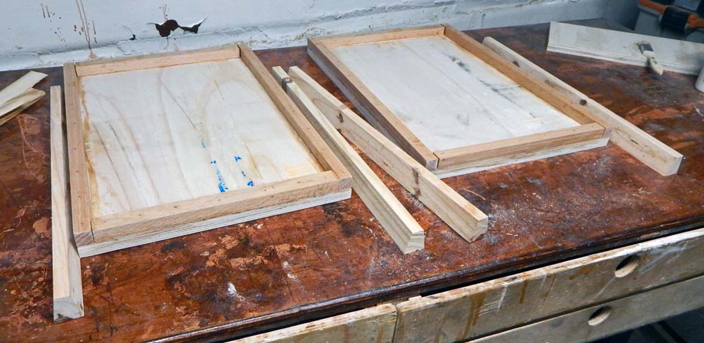
The first two wedges glued and nailed onto each side of the front baffle boards.
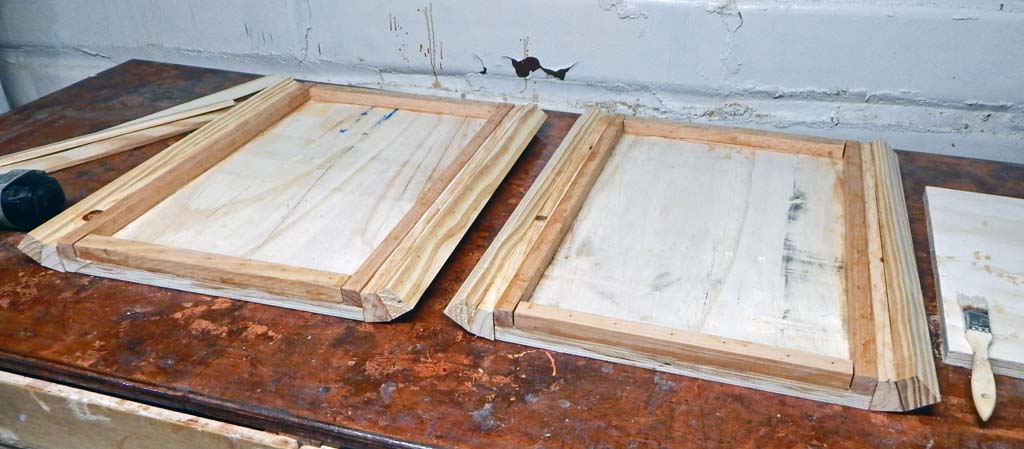
All 6 wedges per side attached to both baffle boards to complete the 135 degree sweeps. 24 wedges in total.
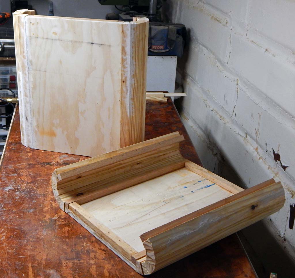
Speaker cutouts added. I used the hole cutout plywood pieces, trimmed on the bandsaw, along with a few pieces of scrap plywood, to double-up most of the front baffle board to 1.5" thick. Plywood circles are difficult scrap to figure out how to re-use. Was nice not to waste the wood. The radiused curves are also about 1.5 inch thick. The whole baffle board and curved corners are about 1.5" thick (except for a few small baffle board areas I was too lazy to fill with scrap).

The backs attached with 2 X 2 pine boards bracing the rear corners.

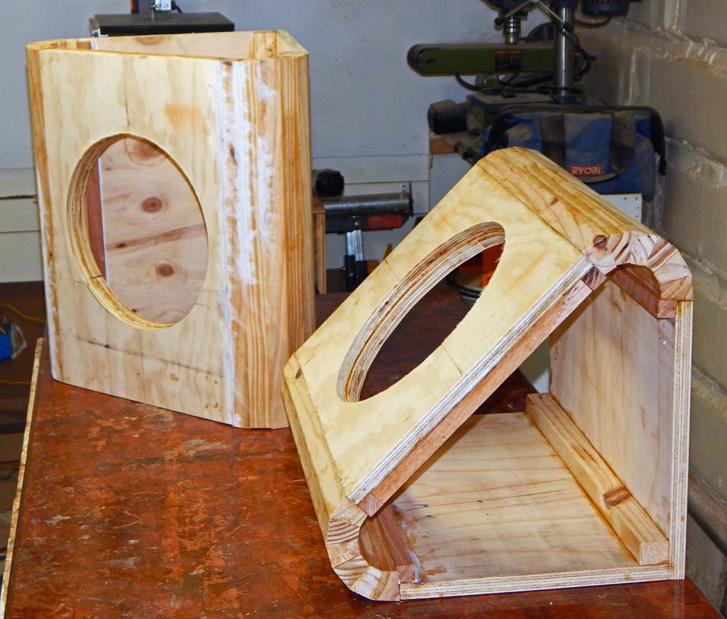
Pictured with the tops and bottoms added, making a total external height of 22 inches. The left cabinet has been routed and rough sanded and the right cab is ready to be routed and sanded. Before attaching the tops and bottoms, I reinforced inside surfaces with a 6 inch waffle grid of 3/4" sticks. I squirted caulk on all seams before adding the top and bottom. Finally added top and bottom bracing and caulked the top and bottom seams by reaching thru the speaker holes, which was not so convenient but do-able.

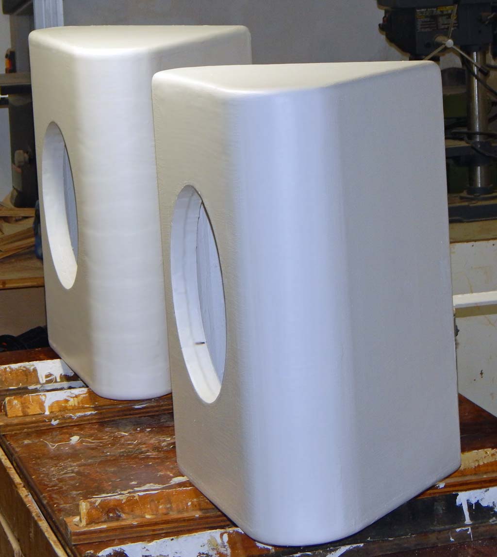
Here are both cabs after wood-filling the incompetent carpenter mistakes and final sanding. I got too impatient sanding the second cabinet. Kept using a heavy 4” belt sander after I should have switched to a smaller easier to contol sander. White horizontal stripes of wood filler where the big sander gouged some spots. A big belt sander can cut too deep in the blink of an eye.
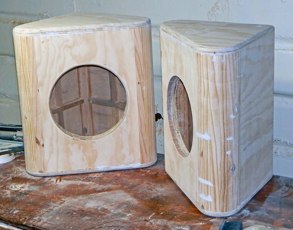
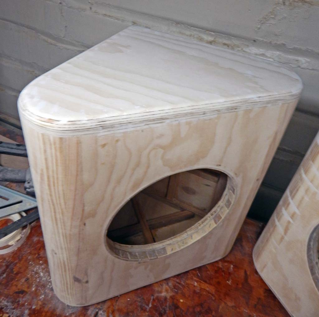
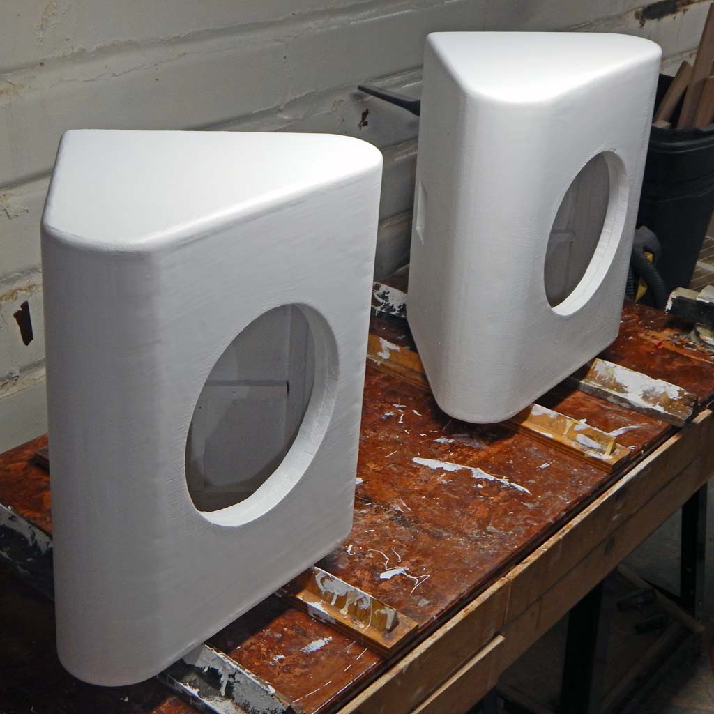
Internal detail photos which also show another carpentry error. I have a big router but never bought or built a good-quality circle cutting jig because I rarely need to route circles. On the earlier subwoofer cab and these coax cabs, I used a small rotozip router because a flimsy rotozip circle jig is the only one I had.
The rotozip itself is strong enough to “slowly” route out 3/4” plywood without burning up the tool. I tightened the circle jig as tight as possible, and took care to prevent the jig slipping out of adjustment. The lightweight circle jig still had some creep. The speaker holes got cut slightly too big. Not too big to work but too big for a “perfect” fit with the rear of the speaker frames.
I bandsaw-cut a bunch of thin wood squares. Glued and stapled the little wood squares around the inner circumference of the speaker holes. Which resulted in proper-sized speaker holes.
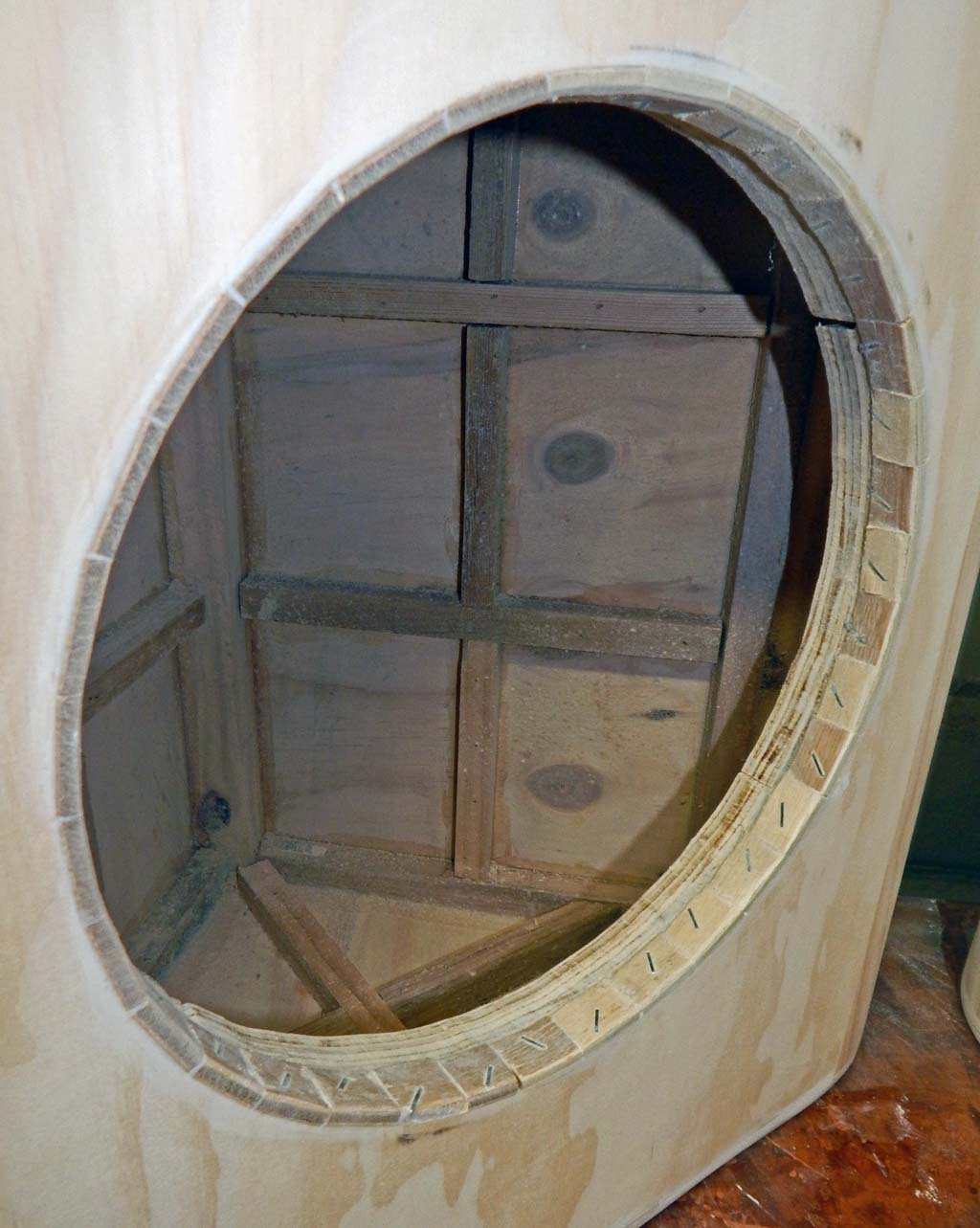
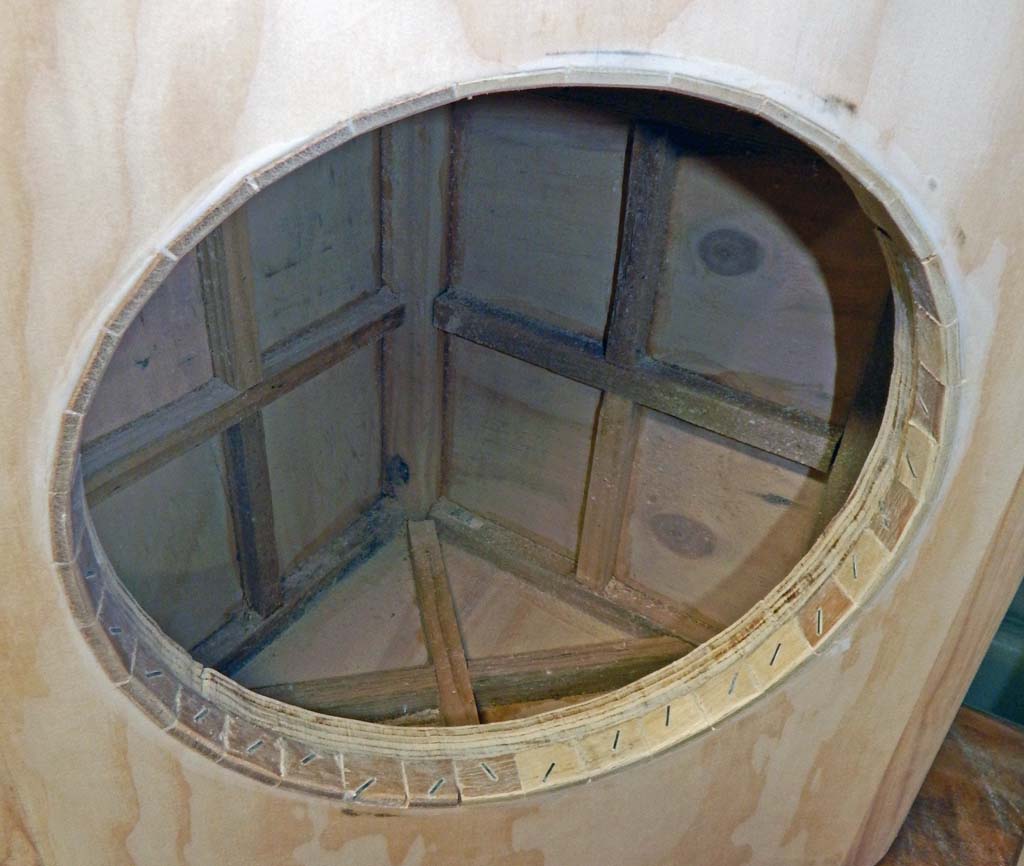
Here they are painted with three coats of Gripper Primer. Gripper dries fast into a very tough finish.

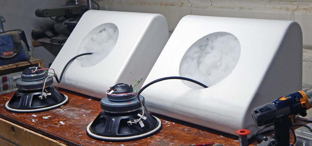
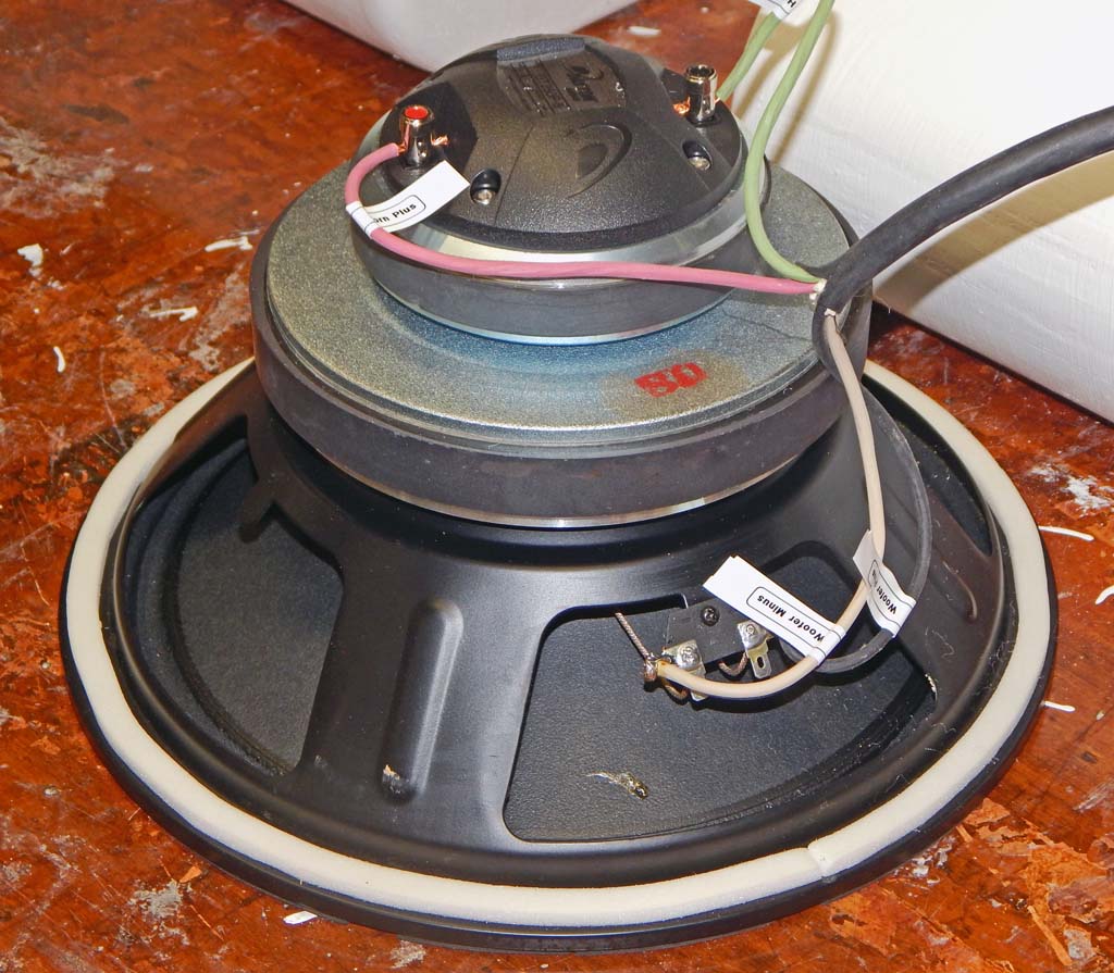
Here are the cabs after filling with polyester pillow stuffing and the speakers wired. I used four-conductor 14 gauge wire with rear dual banana plug jack plates. They are intended for bi-amp only. No passive crossovers.
Here are the speakers as placed for initial setup and testing. The office was a mess after having temporarily removed the "very nearfield" treatments to install the new speakers and pull new four-conductor biamp speaker cables behind the keyboards and absorbers.
The speaker shelf is supported from the floor with two 2X6 boards and two 2X4 boards. The speaker shelf itself (except for a few inches of front lip) is about 3 inches thick. The shelf is not very resonant or wobbly. Perhaps better vibration damping would be called-for-- I used two half-inch sheets of dense closed-cell foam (1 inch total thickness) for isolation between speakers and shelf. The 1 inch closed-cell foam is the only point of contact. The speaker sides do not touch adjacent surfaces.
Because the subwoofer carries the low bass, in my opinion this amount of vibration isolation may be adequate. Speakers vibrating the shelf are supposedly the biggest problem with shelf mounting. Sound travels faster through the shelf than through the air-- If the shelf itself radiates enough audio energy into the air, then the ear may hear “pre-echo” sound from the shelf before hearing direct airborne sound from the speakers. This multi-path delayed sound could cause comb-filter anomalies.
Even at uncomfortably loud near-field SPL, the speaker cabs are thick and solid enough that I can't touch the cabinets and feel obvious vibration. Additionally I can't touch the shelf and feel vibration. Perhaps the shelf could direct-radiate sufficient SPL to cause multi-path comb-filtering even if I can't feel vibration. Tis hard to say with certainty.

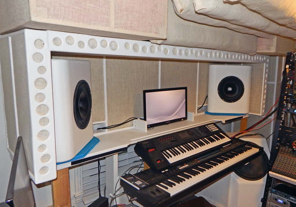
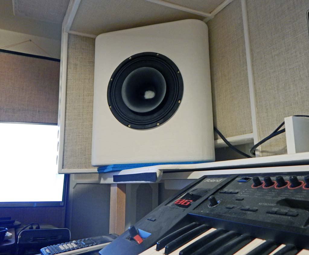
In this picture I was experimenting with small low-density balls of polyester stuffing placed in the horn throats to discover if that would “reduce horn diffraction” or change the frequency response or the sound.
Amplification
The previous system was three-way bi-amped-- One amp driving passive crossovers inside the 2-way JBL monitors and another amp driving the subwoofer-- A two-way DBX driverack performed active crossover between the sub and the JBL mains.
The new system was planned for tri-amping. Requiring an additional amp and an additional active crossover split. The old amps were about 30 years old and I worried about them failing unless they are re-capped.
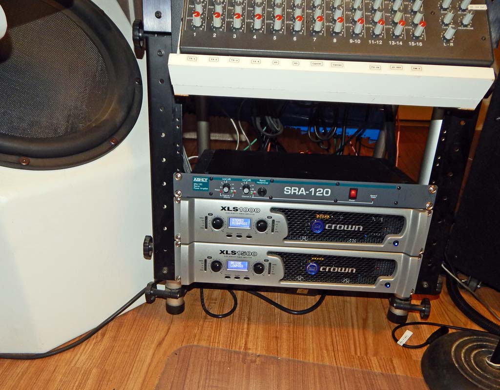
So got two new amps and a “relatively new” used amp. A Crown XLS 1500 for the subwoofer, a Crown XLS 1000 for the coax 12” woofers, and a used Ashly SRA-120 amp for the coax horns.
The XLS amps feature built-in Linkwitz-Riley 24 dB crossovers. Therefore I did not have to buy a new three-way Driverack or some other extra active crossover. The old 2-way Driverack splits between the coax horn the and coax 12” woofer. The XLS amp built-in crossovers split between the coax 12” woofers and the 18” subwoofer.
All three amps have output-relay speaker protection among other mechanisms. The Ashley amp has no fans, and the XLS amps have near-silent fans. The XLS fans would probably get rather loud running full power on a rock'n'roll stage. However when driving low power near-field monitoring the fans are off most of the time. When the fans occasionally turn on for less than a minute, they turn very slow. In low-power operation it is near-silent amplification. Which is great-- If I ever crank the office system enough to speed up the fans then the office would be so loud I wouldn't be able to hear the fans.
Dynamic Range and Crest Factor
I am not expert on this topic. Was aiming for “unlimited dynamic range”. Not literally unlimited. Practically Unlimited would be good enough. The practical restrictions are defined by very nearfield operation and a desire to protect the ears from further damage. I occasionally run the system for a few minutes of louder than 90 dB SPL, Slow C weighted. But I typically monitor no louder than about 90 dB SPL. On long sessions I listen at lower levels, 80 dB SPL or less.
I monitor at about 1 meter distance from the speakers.
The coax Horn driver sensitivity is specd 105 dB 1 watt 1 meter. If one horn were to account for 90 dB SPL then the Ashly amp would need to deliver about 0.032 “long term average” watts from one channel of the amp. With the Ashly amp driven to hit 40 watt transient peaks then theoretically that would deliver 121 dB SPL transient peaks. Which would be a 31 dB crest factor relative to an average long-term listening level of 90 dB.
The coax 12” woofer sensitivity is specd 95 dB 1 watt 1 meter. The XLS 1000 amp is specd 215 watts per channel at 8 ohms. If one woofer were to account for 90 dB SPL then the XLS 1000 would need to deliver 0.316 “long term average” watts from one channel of the amp. With the XLS 1000 driven to hit 215 watt transient peaks then theoretically that would deliver peak SPL of 118.3 dB on one channel. Which would be a 28.3 dB crest factor relative to an average long-term listening level of 90 dB.
The subwoofer sensitivity is specd 88.6 dB 1 watt 1 meter. The XLS 1500 amp is specd 1550 watts at 4 ohm bridged. If the subwoofer were to account for 90 dB SPL then the XLS 1500 would need to deliver 1.38 “long term average” watts. If the XLS 1500 were driven to hit 1550 watt transient peaks then theoretically that would deliver peak SPL of 120.5 dB. Which would be a 30.5 dB crest factor relative to an average long-term listening level of 90 dB.
With all speakers and amps sharing the load, the theoretical crest factor of the sum of all the parts ought to be bigger than 30 dB but I do not know how to calculate a realistic total crest factor. Perhaps real world speaker distortion would not allow this large of a clean crest factor. However, for near-field listening at non-painful levels, peak distortion ought to be rather unlikely.
Preliminary Conclusions
I will post a followup article describing the results in tedious detail. There are some quibbles and uncertainties. Overall I'm happy with the speakers.
The speakers were adjusted to sound quite satisfactory for recreational listening and amateur recording. The system also sounds quite good for playing keyboards. To my ears it sounds pristine clean and well-balanced. Have noticed no distortion from big chords or low keybass. The coax speakers sound fatter to me than the previous small JBL monitors.
The subwoofer vs coax woofers are crossed-over at 80 Hz with 24 dB per octave Linkwitz-Riley slope. The coax woofer vs coax horn are crossed-over at 1 kHz with 24 dB per octave Linkwitz-Riley slope. That is theoretically lower than expected for such a small horn. A more “standard” frequency for this small horn might be closer to 1.5 kHz. But in this situation it seems to be working fine at 1 kHz crossover. Will supply further details in a subsequent article.
Forward to Coaxial Speakers Build Part 2 - Speaker Selection